|
|
Development of the graphic post-processor for the TRAC code
The leading specialists of SSL developed the graphical post-processor on the basis of the programming code TRAC that is used for 3D precise thermo-hydraulic calculations of nuclear reactor.
General characteristic of the TRAC code
The code of improved estimation TRAC has been developed in US Los-Alamos National Laboratory.
Abilities of the graphic post-processor
- 4 matrixes of porosity coefficients, 6 matrixes of hydraulic resistance coefficients, 3 matrixes of hydraulic diameters;
- matrix of volume steam content;
- Animation of more than 50 values outputted by the code and additionally calculated in the post-processor.

Application of graphic means of processing (pre-processor and post-processor) is undoubtedly necessary when 3D codes with dimension more than 10000 calculating cells are used.
Developers of the TRAC code do not supply the graphic means of processing, therefore the special package of programs (programs Fieldview, TracBin, PreVessel, Tracdiff) has been developed in SSL. This package in designated for the following purposes:
- Package of programs puts out the fields of 3D matrixes initial data for graphic processing (diagnostic of 3D arrays of porous coefficients, hydraulic resistances, hydraulic diameters).
- Visual control of solution convergence by calculated fields of vector (6 fields) and scalar (about 40 fields) 3D variables.
- Obtaining the results of local characteristics for the spatial (2D and 3D) fields of vector and scalar variables in graphic and digital forms.
- Tracdiff gets the difference of two problems solutions at the same meshes for all 3D fields of vector and scalar variables.
Output information is:
- Graphic file of results at the given two-dimension plane as the cartograms (in “color” form or as vector field distribution for the phases velocity).
- Text (digital) file of results at the given two-dimension plane as the suitable cartograms. This method is convenient for farther processing by the graphic packages and other applications.
List of parameters for I and II circuits includes: 3D arrays of liquid and steam velocity elements or reduced velocity elements, volume steam-content, temperature of liquid and steam phases, saturation temperature, pressure, saturation pressure, mass steam-content, mass velocity, density of the phases and mixture, sliding coefficient, heat flow density, distribution of heat emission coefficients by every circuit and other parameters.
Simulation of VK reactor
VK reactor is intended to produce heat power as a part of the reactor facility with providing of the coolant natural circulation in all operational modes: start up (heating up, going at power level), operation at power level, shutdown, cooling.
The specific features of VK boiling reactor are:
- Heat power of 750 MW;
- Application of VVER-1000 case with integral package of the primary circuit;
- Natural circulation in the primary circuit;
- Lifetime is 60 years;
- Enrichment of dioxide fuel is 4%;
- Increased safety level comparing with the NPPs existing in the world.
The principle scheme of VK reactor facility is presented below.

Fig. 1. The principle scheme of VK reactor facility
1 – the core;
2 – mixture chamber;
3 – draft tubes;
4 – distribution chamber (DC, I step separator);
5 – axial (centrifugal) separators (AS).
The carried out calculations let to make a conclusion on importance of all initial data conformity. With completely agreed geometry parameters, heat power and resistance coefficients in the elements of the natural circulation circuits, difference between TRAC and ROSA (the chief designer’s code) does not exceed 3% of the value of mutual circuit circulation..
 Fig. 2. Calculation scheme in R-Z geometry.
Liquid speed field (arrows) and steam content fields (color).
Simulation of steam generator PGV-1000
Calculations of PGV-1000 steam production and heat power in 3D geometry demonstrated that difference between TRAC code and the project value does not exceed 2.5%.
Thus, with enough detailed nodalization of the calculation scheme and agreed specification of all initial data, application of TRAC code allows to obtain integral characteristics of the facilities and equipment that are in good conformity with the project data and domestic codes in spite of significant difference in the systems of closing relations accepted in US codes and in Minatom.
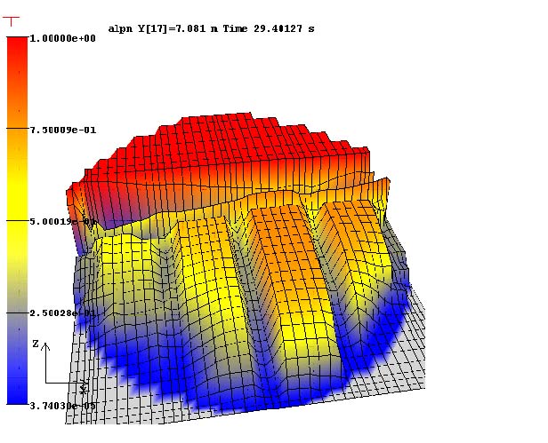
Fig. 3. Field of true volume steam content in X-Z section of steam generator along II circuit (in collectors area)
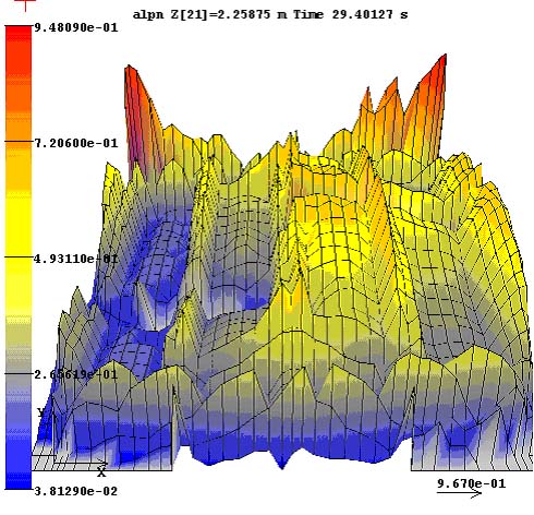
Fig. 4. X-Z section of PGV-1000. Field of volume steam content above the PG tube bundles
Dynamic of PGV-1000 empty along II circuit when the feed water convey is stopped.

Fig. 5. Calculation using TRAC codes of the steam flow rate in PGV-1000 when the feed water convey is stopped,
comparing with the calculations using CORSAR (NITI, 2 versions of the tank model) and CATHARE (France) codes
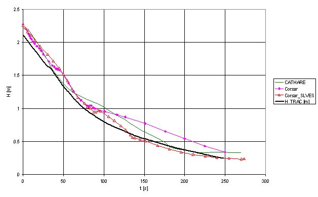
Fig. 6. Calculation of water level change when the feed water convey in PGV-1000 is stopped.
Calculation using TRAC codes comparing with verification by CORSAR (NITI, 2 versions of the tank model) and CATHARE (France) codes.
|